
News Center
Your current location:Home > News CenterNews Center
Key Points for Design of Gas-Powered Pipelines in Cleanrooms
2026/7/1
01 Preparations before Design
Base parameters have been determined.
Classification of Gas Types and Uses
According to the properties of the gases and the cleanliness requirements, clearly define the key points of pipeline design:
Common power gas: Compressed air (instrument air / process air), mainly used for equipment drive and purging, and it needs to control the content of oil, water and particles.
Inert protective gases: Nitrogen, Argon. Used for process isolation and oxidation prevention. The purity (99.9% - 99.999%) and leak-free condition must be guaranteed.
Flammable and explosive gases: Hydrogen, acetylene. Special attention should be paid to explosion prevention, static electricity prevention, and leakage detection.
Combustion-supporting / Oxidizing gases: Oxygen. It must be kept away from grease. The material of the pipelines needs to be degreased.
2. Verification of Process Parameters
Collect the core parameters as the basis for pipe diameter selection, pressure grade determination, and material choice:
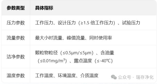
1. Selection of pipeline material: Matching with cleanliness and medium characteristics
The material should meet the requirements of corrosion resistance, no precipitate formation, and easy cleaning, and should avoid contaminating the cleanroom environment or medium:
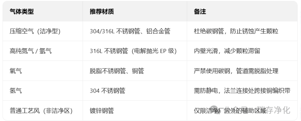
2. Pipe Diameter Calculation and Resistance Control
Calculation Principle: Based on the flow formula Q = v × A (where Q is flow rate, v is flow velocity, and A is the cross-sectional area of the pipe), combined with the allowable pressure loss (generally ≤ 0.1 MPa/100m), the pipe diameter is determined.
Flow rate limitation: Different gases require controlled flow rates to prevent the generation of particles or static electricity due to turbulence:
Compressed air: Main pipe flow velocity ≤ 8 m/s, Branch pipe flow velocity ≤ 5 m/s;
High-purity gas: Flow rate ≤ 3 m/s, reducing friction on the inner wall of the pipeline and minimizing particle generation;
Flammable and explosive gases: Flow rate ≤ 10 m/s. Prevent accumulation of static electricity.
Measures to reduce resistance: Try to use large-radius elbows (R ≥ 3D) as much as possible, and reduce local resistance components such as valves and reducers; for long-distance pipelines, sectional pressure reduction devices should be set.
3. Pipeline layout and installation: Adapted to the characteristics of the clean workshop
Laying method
Overhead laying: This method should be given priority. It should be arranged along the technical interlayers of the clean room and the pipe shafts, which is convenient for maintenance. It should maintain a safe distance (≥0.15m) from other pipelines (such as water supply and drainage, and electrical lines).
Underfloor piping: This method is only applicable to non-clean areas or auxiliary zones. The floor trench must be treated for waterproofing and dust prevention, and drainage points should be set up to prevent water accumulation and contamination.
Underground laying: It is strictly prohibited to use in clean rooms to prevent leakage and dust accumulation.
Layout Principles
Short-circuit principle: Reduce pipeline length, decrease pressure loss and gas retention time.
Uninterrupted design: The pipelines are connected as much as possible in a straight line. Valves and joints are avoided being placed directly above the core area of the clean room to prevent leakage from contaminating the products.
Zone control: Cut-off valves are set up according to the cleanliness level for each zone, which enables maintenance in one area without affecting the operation of other areas.
4. Cleanliness Assurance Design
The core requirements for gas pipelines in clean workshops are to prevent gas contamination and to avoid the generation of pollutants by the pipelines themselves. This needs to be controlled at multiple stages:
Pipe inner wall treatment: High-purity gas pipelines need to undergo electrolytic polishing (EP) or passivation treatment. The surface roughness Ra should be ≤ 0.8 μm to reduce particle adsorption and retention.
Gas purification device configuration:
Compressed air: Install three-level filtration (coarse filter → fine filter → activated carbon filter) + refrigerated dryer / adsorption dryer to ensure that the dew point meets the standard.
High-purity gas: Terminal is equipped with membrane filtration or sterilization filter (filtration accuracy ≤ 0.2 μm), which is installed at a location close to the gas usage point.
Scrubbing and Passivation: After the pipeline installation is completed, it is necessary to conduct segmented scrubbing with dry nitrogen or clean air (flow rate ≥ 20m/s) to remove welding slag and dust from the pipeline; for high-purity gas pipelines, passivation treatment is also required to form a dense oxide film, preventing the release of metal ions.
5. Safety Design: Special Requirements for Hazardous Gases
For flammable and explosive gases as well as gas that supports combustion, strict safety regulations must be followed:
Explosion-proof design: Gas pipelines for hydrogen, acetylene, etc., must not pass through firewalls or floors. Fire dampers need to be installed; pipeline valves should be of explosion-proof type, and electrical equipment should be selected with models matching the explosion-proof grade.
Anti-static design: Copper braided strips are used to connect the pipe flanges and joints, with the grounding resistance being ≤ 10Ω; The entire pipeline system is grounded to prevent the accumulation of static electricity.
Leakage detection: Gas leakage alarms should be installed in the gas storage area and at key points of the pipelines. Oxygen leakage alarms should be placed at a high position indoors (where the oxygen density is greater than that of air), while hydrogen leakage alarms should be set at a low position indoors (where the hydrogen density is less than that of air).
Emergency shut-off device: Emergency shut-off valves are installed at the gas source inlet and the gas usage point, and they are linked with the leakage alarm system. In case of leakage, the gas source will be automatically cut off.
03 Selection of Valves and Accessories
Valve type
High-purity gas: Preferentially use diaphragm valves and ball valves, as they have good sealing performance and few dead corners; do not use gate valves (they are prone to accumulate dust).
Common gases: Butterfly valves and globe valves can be selected, with good cost-effectiveness.
Material requirements: The material should be consistent with that of the pipeline. For high-purity gas valves, 316L stainless steel should be selected, and the sealing components should use clean materials such as PTFE.
Other attachments
Pressure gauge / Flow meter: Installed at a position convenient for observation. For high-purity gas systems, oil-free type instruments should be selected.
Condensate water discharge valve: An automatic drain device is installed at the lowest point of the compressed air pipeline to regularly discharge condensate water and prevent it from being introduced to the gas usage points.
Sampling port: A sampling port is set up on the high-purity gas pipeline to facilitate regular detection of the purity and cleanliness of the gas.
04 Key Stages of Construction and Acceptance
Welding Requirements
For the welding of clean pipelines, argon arc welding (TIG) is preferred. The inner wall is filled with argon to provide protection and prevent the formation of oxide layers during the welding process.
The welds must undergo 100% radiographic testing to ensure there are no defects such as pores or cracks; the weld surface should be smooth and flush with the inner wall of the pipeline.
Acceptance criteria
Pressure test: When the design pressure is ≤ 1 MPa, the test pressure is 1.5 times the design pressure; when the design pressure is > 1 MPa, the test pressure is the design pressure + 0.5 MPa, and it is held for 30 minutes without leakage.
Cleanliness testing: The particle counter is used to measure the content of particulate matter in the pipeline. For high-purity gas pipelines, purity testing (gas chromatography method) is required.
Air tightness test: Conduct an air tightness test using nitrogen at the design pressure. Maintain the pressure for 24 hours, and the pressure drop should be less than or equal to 0.5%.
05 Key Points for Operation and Maintenance
Regularly check the pipeline pressure and leakage conditions. The high-purity gas system undergoes a purity test once a month.
Regularly replace the filter element of the filter, and the adsorbent of the compressed air dryer needs to be regenerated or replaced regularly.
Avoid frequent start-stop operations of the pipeline system to reduce the damage to the pipes and valves caused by pressure fluctuations.