News Center
Monitoring design of Air conditioning DDC system
2025/8/29
The DDC system is the technical form of BAS. The abbreviation of DIRECTDIGITALCONTROL in English, translated as "Direct Digital Control".
The air conditioning DDC system utilizes computer control technology to input various signals (such as temperature, pressure, flow rate, status, etc.) in the air conditioning system into the computer through input devices. After being processed by corresponding programs, the processed signals are output through output devices to control the corresponding actuating mechanisms.
2. Types of Signals in DDC Systems
Signals are classified into four types based on whether their output and input can be directly accepted by microcomputers or actuators: digital input (DI), digital output (DO), analog input (AI), and analog output (AO) signals.
The analog signal corresponds to a certain amount of voltage or current value, which is related to the characteristics of the sensor's output signal.
Common analog input signals in air conditioning automatic control systems: temperature, humidity, pressure and flow, pressure difference, etc. Analog output signal: Electric air valve and electric water valve to be controlled.
Digital input signals include: the operating status of fans, water pumps, cooling tower fans, motors, filter clogging status alarms, differential pressure switches, liquid level switches, switch signals, anti-freezing protection, etc.
Digital output signals include: control of solenoid valves, control of two-position electric water valves, start and stop control of equipment such as water pumps, fans, and cooling towers.
3. Main Functions of the Air Conditioning DDC Monitoring System
The air conditioning DDC system can realize various control functions of the air conditioning system in buildings and also has various management functions.
1) Energy control and management function. That is, based on the actual cooling and heating loads of the building, the air system and water system in the air conditioning system are controlled, and the operating status and parameters of the cooling and heating equipment are automatically controlled to make the entire air conditioning system reach the best energy-saving state.
2) Regulate, control and monitor the relevant parameters of the air conditioning system and its cold and heat source systems, and monitor the operation of air conditioning equipment.
3) Start and stop control of air conditioning equipment such as water chillers, pumps, and fans at specified times to achieve energy-saving purposes.
4) Automatically accumulate the operating time of air conditioning equipment and issue maintenance period alarms to facilitate the replacement or repair of related equipment, extend the service life of the equipment, and improve the operational quality of the equipment.
5) According to the operating time of the air conditioning equipment, it automatically switches between working and backup equipment to maintain the good working condition of the equipment.
6) Measure the energy consumption of the air conditioning system and charge it.
7) Automatic generation, printing and query of various property management texts.
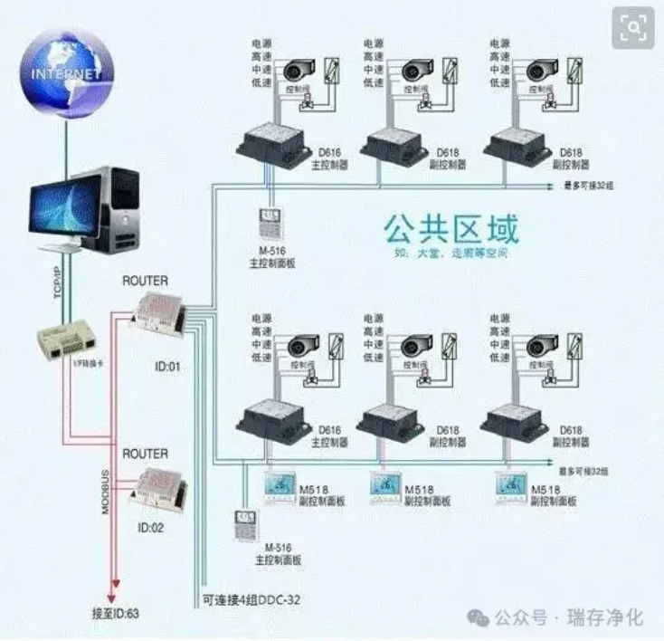
4. Composition of the Air Conditioning DDC System
1) Clock: It is used to adjust and control various input and output data, as well as various operation times.
2) Program memory: It stores various application programs, that is, the control programs compiled by users to control various air conditioning systems.
3) Working memory: It is used for reading, writing, random access and temporary access to data.
4) Multi-channel input and output controller: The multi-channel input controller can send input signals into the A/D converter to convert analog quantities into digital quantities, which are then input into the microprocessor for operation. The operation result is input into the D/A converter, and then sent to the transmitter and actuator through the output controller.
5) Relevant software for the DDC control system: including operation software and application software.
5. Examples of Air Conditioning DDC Control
The DDC control of air conditioning includes the control of the air conditioning air system and the air conditioning water system. The following are examples to illustrate them respectively.
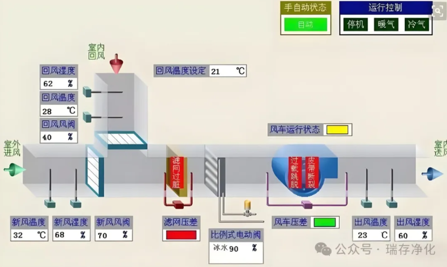
5.1 Air Conditioning Air System: (Taking the control of fresh air units as an Example)
The fresh air unit is one of the main equipment in the air-water system air conditioning form. The quality of its control directly affects the working quality of the entire air conditioning system. Generally, a fresh air unit consists of a fresh air section, a filtration section, a coil section (the composite coil corresponds to the second pipe, and the fourth pipe is the surface cooler and heater), a humidification section, a supply fan section and the corresponding maintenance section. Some are also equipped with energy recovery devices, and the control instructions are shown in the figure.
1) Start and stop the fresh air unit.
2) After the fan of the fresh air unit starts, the interlock of the fresh air valve opens.
3) Control the opening and closing of the electric valve MD1 for the cold and hot coil according to the temperature T1. After the switch between winter and summer operation, in winter, the on and off of the humidifier's electromagnetic MD2 is controlled based on the humidity H.
When the temperature T1 drops to the anti-freezing alarm temperature, the power supply to the fan will be automatically cut off. Interlock to close the fresh air valve VD, fully open the electric water valve MD1, and issue an alarm signal.
When the dust accumulation in the filter reaches a certain level, the differential pressure switch will issue a clogging alarm signal.
When the machine stops, the fresh air valve VD interlocks and closes, the electric valve MD1 is fully closed, and the solenoid valve MD2 is closed.
7) Monitor the operating status of the supply fan.
5.2 Air Conditioning water system
This system is a single-stage pump variable flow system. The connection pipes of the air conditioning terminal devices are two-pipe systems, and the chiller operates in a one-to-one manner with the cold water pump, cooling water pump, and cooling tower. Three cold water pumps and three cooling water pumps are each set up, with two in use and one as a backup. They can be switched and operated according to the working conditions of the chiller and the cooling tower.
1) System startup sequence: Start the cooling tower fan, open the cooling tower water valve MD1, start the cooling water pump, wait for 30 seconds, then open the cold water valve MD2, start the cold water pump, wait for 30 seconds, and start the chiller. Take the reverse order of the system shutdown methods.
2) Start the chiller according to the FS signal of the water flow switch.
3) Calculate the cooling load by the product of the cold water flow rate F1 and the difference between the supply and return water temperatures T1 and T2, and control the number of chiller units. When only one unit is in operation, perform frequency conversion control on that unit.
4) Adjust the opening degree of the electric valve MD according to the difference between P1 and P2 (the pressure difference between the supply and return water of the system). According to the load conditions of the terminal equipment of the air conditioning, adjust the bypass flux to keep the chiller operating at a constant flow rate.
5) All equipment, including the chiller, cooling water pump, cold water pump, electric valve, etc., should be controlled on and off, and be connected to the random control cabinet of the chiller, and the signal should be transmitted to the main control room.
6) Refrigerant leakage alarm, and it is linked with the emergency exhaust equipment of the system unit and the machine room.
7) Monitor the operating status, fault display and alarm of the chiller, cold water pump, cooling water pump and cooling tower, and record the operating time.
8) Monitor the electric control valve MD. The switch status of MD1 and MD2.
9) All parameters such as temperature, pressure and flow rate can be monitored and recorded, and can be printed into tables.
The above is only a brief description of the air conditioning DDC system. In actual engineering design, the DDC control design of air conditioners is a technical requirement put forward by the air conditioning specialty, and is implemented and completed by the electrical and automatic control specialties. To do a good job in the DDC control of air conditioners, closer cooperation and mutual understanding among specialties are even more necessary.